visualculture
Path to Lyspial (OE-003)
User Manual
Overview
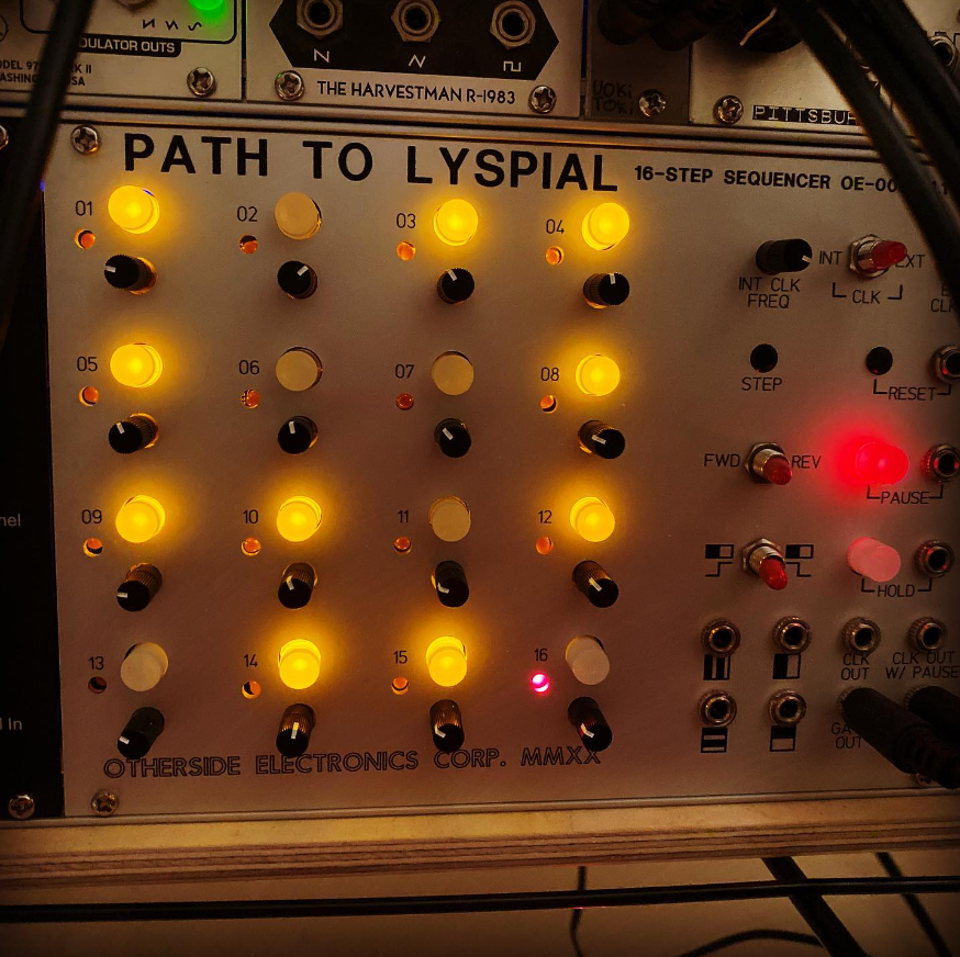
The “Path to Lyspial” (OE-003) is a 16-step sequencer for the Eurorack platform. The classic sequencer use case is to pair it with a synthesizer module to sequence melodies, basslines, or other musical patterns. One of the great things about Eurorack, however, is that pretty much any output on any module can be connected to any other input on any other module: the signals generated by this module can control any parameter you want in your patch. For example, you could use it to rhythmically sequence the cutoff frequency of a filter (for an example of this, see the track called CHKDSK on Ephemeron).
First I will go over all of the different functions of this module. Think of this section as a user manual for the Path to Lyspial. Then afterwards I will discuss its design under the hood.
Sequencer Grid:
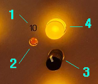
- A number printed on the panel indicating the step’s position in the 16-step sequence
- A red LED indicating which step the sequencer is currently on
- A knob for adjusting the CV (control voltage) output of the step. This would control the pitch of the current step in the traditional sequencer use case.
- An illuminated pushbutton for choosing whether the gate output for the step is high or low. This would control whether the current step is a note or a rest in the classic sequencer use case. When the button is illuminated, that means the step will cause the gate output to go high. When it is not illuminated, the gate will stay low when the sequencer reaches the step. The state can be toggled by pushing the button.
Clock section:
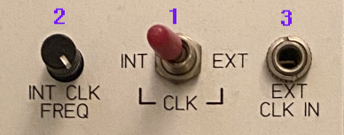
- In the middle there is a switch which controls whether to use the internally generated clock signal or an external clock signal.
- On the left is a knob which controls the frequency of the internally generated clock signal. Turning it counterclockwise will make the sequencer move through the steps at a slower tempo. Turning it clockwise will increase the tempo.
- On the right is a jack for patching in a clock signal from somewhere else.
In general, if you want to use this module as a master clock source, use the internally generated clock. If you want to slave it to other modules, use an external clock and patch it in from some other source.
Step button:
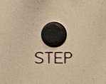
- If you are synchronizing this sequencer with another sequencer and the sequences are not starting on the same step, you can press the step button to “nudge” the sequence back a step.
- If you use no clock, you can manually step through the steps however you like by pressing the step button. You could use this to play your own rhythms manually, or you could use it to trigger events elsewhere in your patch.
Reset:
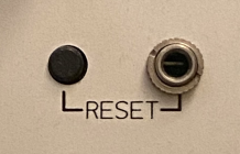
This section has a pushbutton as well as an input jack. When the button is pushed or when the jack receives a high signal, the sequencer will go back to the first step regardless of where it currently is in the sequence. The obvious use for this is if you want to start the sequence from the beginning at any point. But another way you can use it is to create sequences that are shorter than 16 steps.
Pause/Hold section:
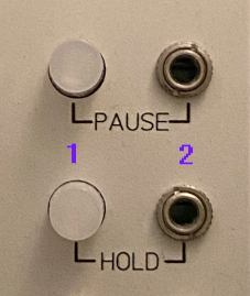
- An illuminated pushbutton for engaging or disengaging the function.
- A jack for patching in an external control signal. A high voltage will engage the function. A low voltage will disengage it.
Pause: When pause is engaged, the sequencer will stop moving through the steps. The CV and gate outputs will remain whatever the current step is. The clock will keep going, but it won’t affect the position of the sequencer. The external clock also will not affect the position.
Hold: Hold is similar to pause in that the sequencer will stop advancing, but it will keep sending a gate signal in sync with the clock. The effect is that the sequencer is playing the current step over and over, rather than the whole thing being paused.
Forward/reverse switch:
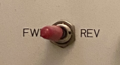
This is pretty straightforward: when the switch is set to forward, the sequencer will advance through the steps in order from 1 to 16. When the switch is set to reverse, the sequencer will advance through the steps in reverse order from 16 to 1.
Auxiliary rhythm section:
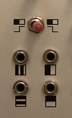
This section contains four output jacks that generate signals that are subdivisions of the clock. The patterns below the jacks represent the signals that the jacks put out. Imagine the square pattern is laid over the 4x4 grid of steps. On a step falling in the black region, the signal will be low. On a step falling in a white region, the signal will be high. Therefore the upper left jack will output low, high, low, high, etc. The upper right jack will output low, low, high, high, etc. You can use the switch above the jacks to invert the patterns, so that on steps falling in the black regions the signal will be high, and for the white regions it will be low.
These outputs are useful for triggering drums to make simple drum patterns, or for triggering other modules to synchronize them with this sequencer. The signals can also be processed or combined using other modules to make them more complex. These outputs can also be fed back into the reset jack to easily create sequences of 8, 4, or 2 steps in length if needed.
Main output jacks:
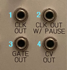
- CLK OUT – this jack outputs the internal or external clock, whichever you are currently using.
- CLK OUT W/ PAUSE – this jack outputs the same clock, but it outputs a steady low signal when the pause function is engaged. This is useful if you want to pause other modules that are synced to the same clock.
- GATE OUT – this jack outputs high when the current step’s pushbutton in the grid is illuminated and low if it is not illuminated.
- CV OUT – this jack outputs a voltage between 0V and 10V, corresponding to the position of the potentiometer of the current step. Usually used for controlling the pitch of the synthesizer being sequenced, but can be used to control other parameters if desired (e.g., filter cutoff frequency).
Additional Information
In this section I will go into more detail about the technical aspects of the Path to Lyspial as well as the design process and some additional background about the module.
The name of the module
The name "Path to Lyspial" was inspired by a short story by Clark Ashton Smith called "Sadastor". In the story, a demon recounts a time when he encountered dying planet on which he heard the singing of a siren. He followed it down into a chasm which had held water at some point but was now completely dry. At the bottom in a dwindling pool was the siren Lyspial who explained that when the pool eventually disappears, so too will she. The demon offered to take her to another more vibrant world, but she refused, saying "I was born of the waters of this world, and with its waters I must die." (I also printed this line on the back of one of the PCBs.) I liken the crafting of the 16-step sequence using the module to the twisting canyon that Lyspial is at the bottom of.
Design considerations
From the beginning I knew I wanted this module to have no menu diving. Each function has one component (knob, button, switch, etc.), and each component has one function. Menus and button combinations are great for saving rack space, but they come with the cost of sacrificing immediacy. If there is some parameter I want to change, I want to be able to look at the module and instantly know what I need to do. Modules with hidden functions always have me referring back to the manual which really takes me out of the music making process. With that said, I will admit this module takes up quite a bit of space.
Another thing I knew I wanted was for this module to be CPU-less, constructed using only discrete logic components. This was mostly an aesthetic choice. A microcontroller would provide more flexibility, future reprogrammability without having to print new PCBs, and simpler PCB design. But there is something I like about the immediacy and the physicality of the "software" being laid out in all these chips on the board, rather than existing as intangible code being executed on a CPU.
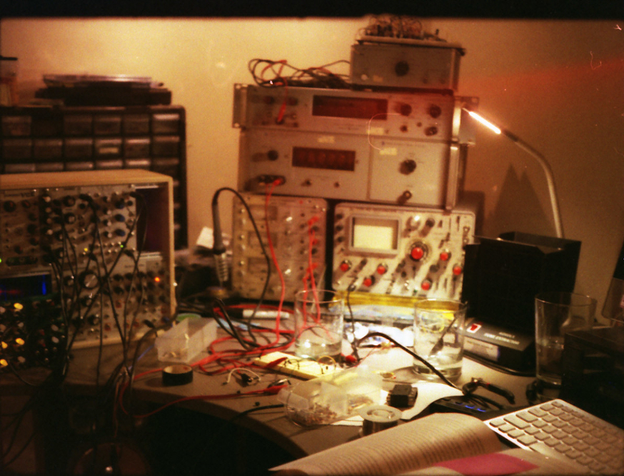
As an aside, if you like designing circuits with discrete logic components or want to learn more about it, I would highly recommend the CMOS Cookbook by Don Lancaster. I had this book at the ready the entire time I was working on this project. It is useful for quickly finding the pin layout and other specs of any CMOS chip, but it is also great for inspiration. Just browsing through the different chips and reading some of the design sections will give you so many ideas.
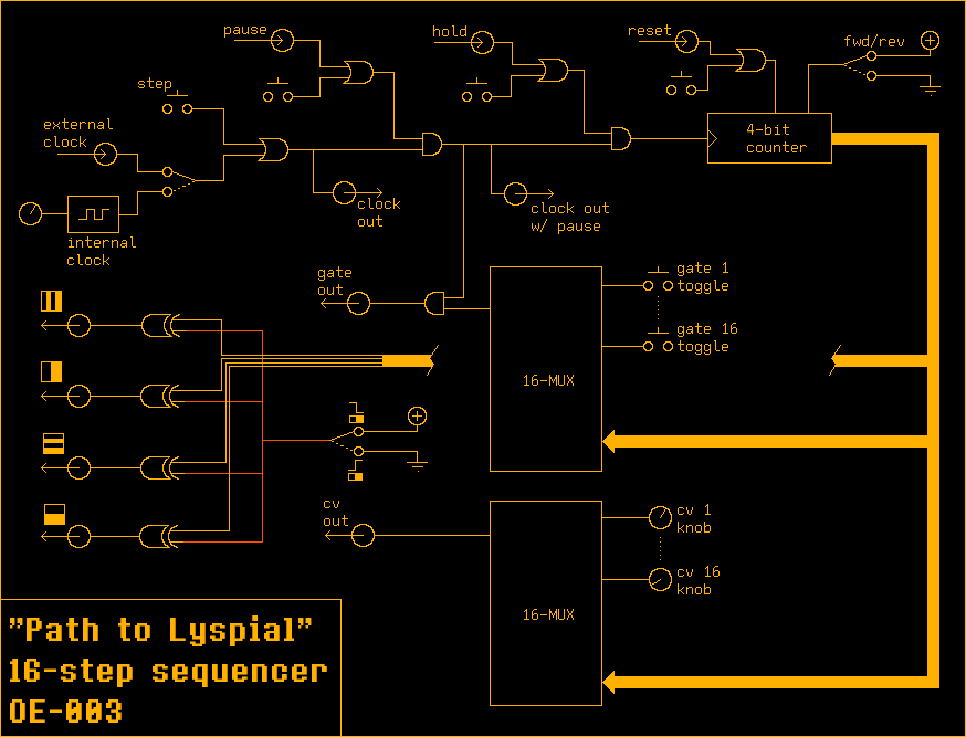
Block diagram
