visualculture
Eurorack video monitor (OE-004)
Description
The purpose of this device will be to provide a convenient way to preview a composite video signal by fitting a small screen into a Eurorack module. It will have one composite video input and two composite video outputs. The screen will display the signal coming in through the input. The two outputs will be the same signal run through a buffer for each output so that it can be sent to external monitors. I may decide to expand the functionality as development progresses.
When performing live visuals, I often rely on a small CRT next to my gear to see what I'm doing since it's not always convenient for me to look at the projection screen or wherever the visual feed ends up going. This works well enough, but carrying around a CRT just to have a preview can be somewhat cumbersome. As I am incorporating more and more Eurorack modules into my signal chain, a module with a small screen would be a perfect solution.
This idea is by no means original. Several modules like this already exist (including the LZX LiquidTV and the Razmasynth Telewizor) but they are generally hard to find. Plus I enjoy the DIY process, so I decided I would make my own.
Devlog
11/15/26: Screen assembly plans
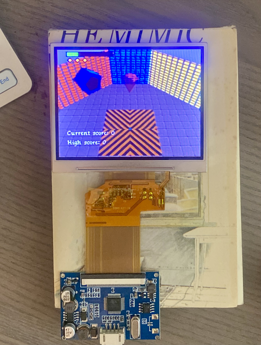
The first step I took was to find a screen that would work for this. I wanted it to be small and thin, work with NTSC composite video, and able to be powered by the standard voltage supplied by the Eurorack platform (so at most 12 volts). This one on Amazon looked perfect for the requirements. The screen is 2.5"x3"x0.14", it has 2 composite inputs, and it runs on 12 volts. It also automatically detects whether the signal is NTSC or PAL and adjusts the display as needed.
I ordered it and it arrived a few days ago. To make sure it worked as expected, I connected it to a 12V power supply and then hooked up the composite out of my N64 to the tiny screen. I tested it with my homebrew N64 game, Mysterious Barricades, and it looks great!
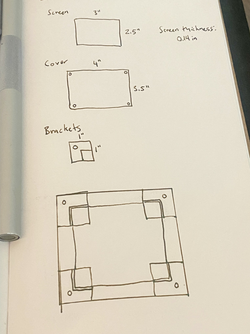
The next problem I wanted to tackle was how to fix the screen to the front panel of the module. I didn't want to use anything involving adhesive (like glue or tape) to avoid messiness or risk of failure as the materials age. I also wanted to avoid putting excessive pressure on the screen to avoid damaging it. The solution I came up with is custom brackets which I will 3d print.
The full assembly will consist of four layers: the aluminum front panel → a thin layer of clear, rigid plastic to protect the screen → the screen itself → the four 3d printed brackets. Four screws will be used to hold everything together. They will go through the front panel, the screen protector, and the brackets. Everything but the screen itself.
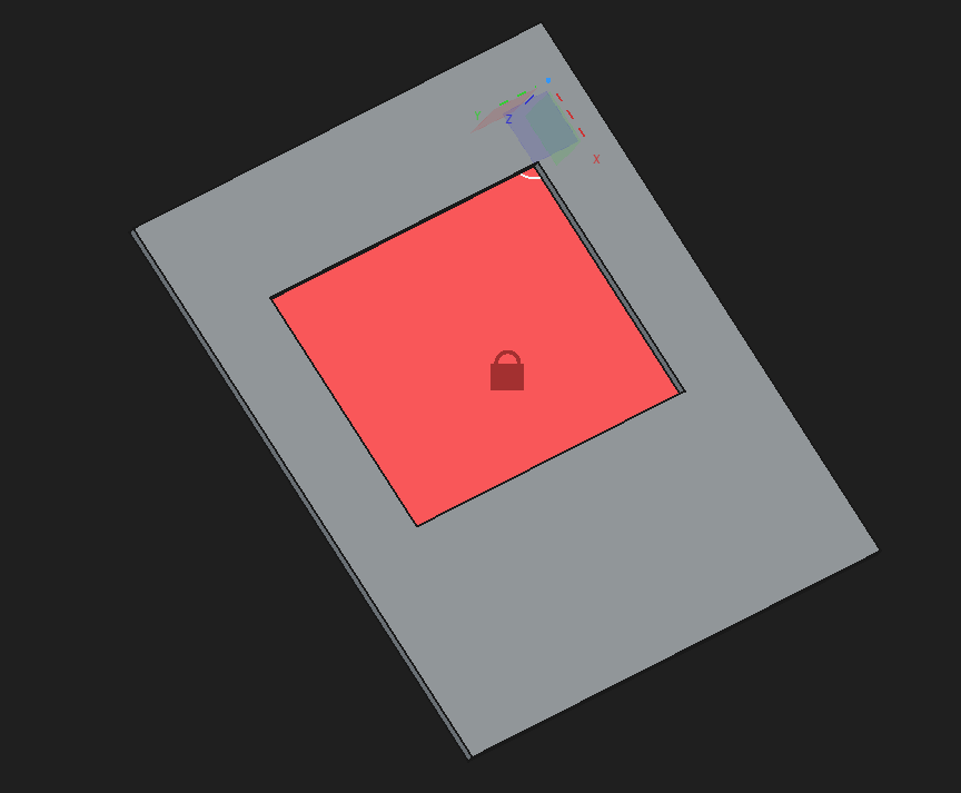
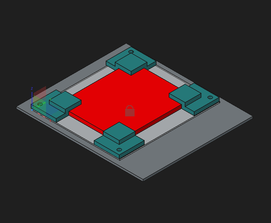
To fully illustrate my idea for the screen assembly I created a mockup in FreeCAD. This is my first time using the software so I'm sure there's a lot I'm not doing correctly, but for now it serves its purpose of visually explaining the assembly.
The materials in the mockup are color-coded: the front panel is the large grey part, the screen protector is transparent/light grey, the screen is red, and the 3d printed brackets are blue. (The screws are not shown, but their placement is indicated by the holes in the brackets. Also not shown are the screws in the corners of the front panel for installing it into the Eurorack case, nor the RCA jacks for the composite video in/outs.)
The next step will be to breadboard the output buffers to make sure they work as I am envisioning. My plan is to use an LM6172 for the output buffers, an op-amp with a very fast slew rate suitable for the relatively high frequencies of composite video signals. I ordered several of those and expect them to arrive in the next few weeks.