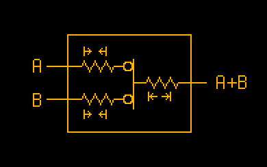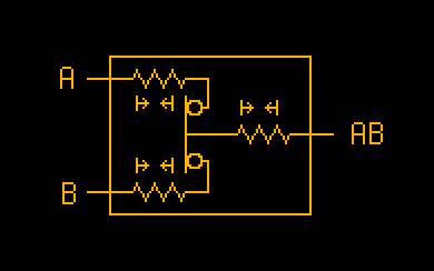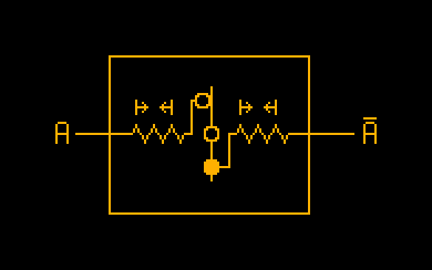
An "or gate" outputs a 1 if at least one input is 1. If all inputs are 0 it outputs 0.
This is the simplest of the three designs. If either of the input dowels get pushed in, they push the output dowel out.
Logic gates are the building blocks of digital devices. They have one or more inputs and one output. The inputs and outputs deal with binary signals whose states are represented abstractly as either 1 or 0. The state of the output changes based on the states of the inputs. Each type of logic gate has a rule for determining the output based on the inputs.
Most logic gates deal with electrical signals. This page outlines some designs I came up with for logic gates that deal with "kinetic signals".
These designs would be constructed chiefly from wooden dowels and springs. The lines in the drawings represent the dowels and the zigzags represent the springs. When a spring is accompanied by arrows pointing inward, that means it is stretched and wants to shrink back to its resting state. When accompanied by arrows pointing outward, it is compressed and wants to expand back to its resting state. A hollow circle indicates two pieces in contact with each other but not connected to each other. A solid circle indicates the pieces are connected.
With electrical signals, a 0 represents 0 volts, and a 1 represents a higher voltage (usually 5 volts). This is how the "kinetic signals" I had in mind would work: each input of one of these gates is a wooden dowel that can be pressed forward. When the dowel is pressed forward, this would be the "1" state. The dowel is spring-loaded, so when it stops being pressed it will pop back out. When the input dowel is not being pressed, this would be the "0" state. Similarly, the output is also a wooden dowel that will move forward or back depending on the states of the input dowels. When the output dowel is retracted, that is the "0" state. When it is popping out that is the "1" state.
I don't know if these would have any practical application but it was fun to think about how they would be designed. I may try to think of how to design the other gate types in the future (XOR, NAND, etc). Also I have no background in mechanical engineering so my diagrams may be weird. If you have any suggestions about how they could be improved let me know.

An "or gate" outputs a 1 if at least one input is 1. If all inputs are 0 it outputs 0.
This is the simplest of the three designs. If either of the input dowels get pushed in, they push the output dowel out.

An "and gate" outputs a 1 only if all of the inputs are 1. If any of the inputs are 0, the output is 0.
In this design, the spring on the output dowel wants to push it outward, but it is held back by the input dowels hooked around it. The springs on the input dowels must be stronger than the spring on the output dowel, so that even when one input dowel is pushed in, the other one still holds the output dowel in place. It is only when both of the input dowels are pressed in can the spring on output dowel retract and push the output dowel outward.

A "not gate" (also called an inverter) is a single-input gate. Its output is simply the opposite state of the input. If the input is 1, the output is 0, and vice versa.
This design uses a dowel that rotates about an axis (the circle in the center). When the input dowel is pressed in, it rotates the inner dowel which then pulls the output dowel inward. When the input dowel is not pressed, the inner dowel rotates back to its initial position and pushes the output dowel back out.